
3D Printed Hydraulic Manifolds & Valve Blocks in AlSi10Mg and 316L
Where Conventional Hydraulic Manifolds Reach Their Limits
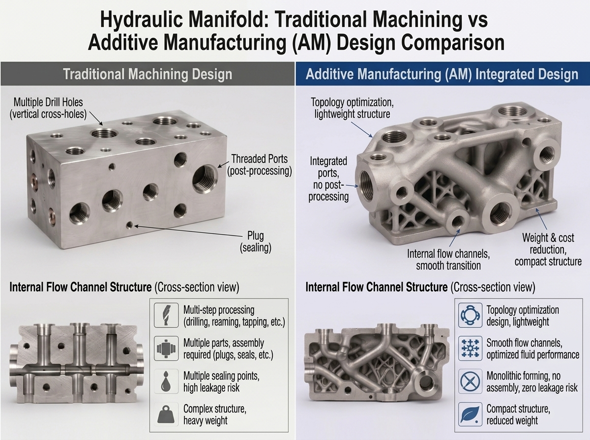
CNC machining and casting remain effective for many hydraulic components, but complex flow routing, multiple plugs, space constraints and frequent design changes can increase system complexity.
Cross-Drilled Flow Paths
Straight drilled passages and sharp intersections can create unnecessary changes in flow direction, turbulence and pressure loss.
Plugs, Joints and Sealing Interfaces
Auxiliary drillings often require plugs, seals or additional connections, creating more interfaces that must be manufactured, assembled and inspected.
Weight and Packaging Constraints
Conventional solid blocks may contain material that is not structurally or functionally necessary, making lightweight and compact system integration more difficult.
Limited Design Iteration
CNC tool access restricts internal routing, while cast designs may require tooling changes when the flow path or component layout is updated.
From Cross-Drilled Passages to Integrated Flow Paths
Conventional manifolds rely mainly on straight drilled passages and sharp intersections. LPBF enables curved internal channels and more direct fluid routing without the same machining-access limitations.
Proven Applications for Aluminum 3D Printed Hydraulic Components
We focus on complex, high-value fluid-control components where LPBF can provide meaningful engineering value.
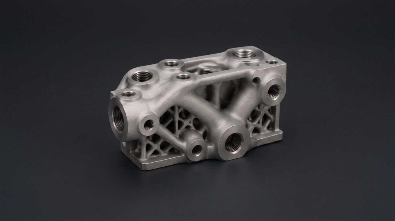
Hydraulic Manifolds and Valve Blocks
Designed for compact hydraulic routing and functional integration in systems where conventional cross-drilling limits channel geometry and installation space.
Core Advantages
- Materials: AlSi10Mg and 316L Stainless Steel
- Typical Applications: Mobile Hydraulics, Robotics, Aerospace, Industrial Automation and Off Highway Equipment
- Integrated Flow Routing: Curved internal passages can replace sharp cross drilled intersections and create more direct connections between hydraulic functions.
- Fewer Plugs and Joints: Integrated channels can reduce auxiliary drillings and external process plugs while minimizing potential leak paths.
- Compact and Lightweight Design: Internal circuits can be arranged around functional interfaces to reduce unnecessary material and installation space.
- Part Consolidation: Multiple blocks, tubes or connectors may be integrated into a single printed component.
- Machined Critical Interfaces: Threads, ports, sealing faces and mounting surfaces can be CNC machined after printing.
- Project Specific Validation: Pressure testing, leak testing and internal channel inspection can be included according to agreed requirements.
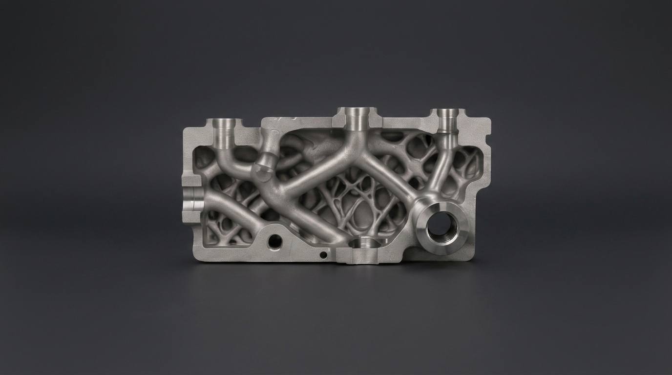
Compact Fluid Distribution Components
Designed to route multiple fluid paths within a restricted installation envelope while maintaining defined ports, interfaces and functional connections.
Core Advantages
- Materials: AlSi10Mg and 316L Stainless Steel
- Typical Applications: Test Equipment, Industrial Automation, Energy Systems, Robotics, Aerospace and Process Equipment
- Multi Circuit Integration: Multiple supply, return and control paths can be routed within one compact component.
- Installation Space Optimization: Internal channels can be arranged around mounting points, sensors, valves and surrounding equipment.
- Functional Consolidation: Separate tubes, connectors and distribution blocks may be combined into fewer manufactured components.
- Defined External Interfaces: Ports, threads and mounting features can remain aligned with existing system connections.
- Material Selection: AlSi10Mg supports lightweight designs while 316L provides greater corrosion resistance for demanding environments.
- Cleaning and Inspection Planning: Channel geometry, powder escape paths and inspection access are reviewed before manufacturing.
- Verification Options: CT scanning, borescope inspection, flow testing and pressure testing can be included when required.
Material Options for Hydraulic Manifolds
Material selection should consider weight, corrosion resistance, fluid compatibility, temperature, mechanical requirements and post-processing needs.
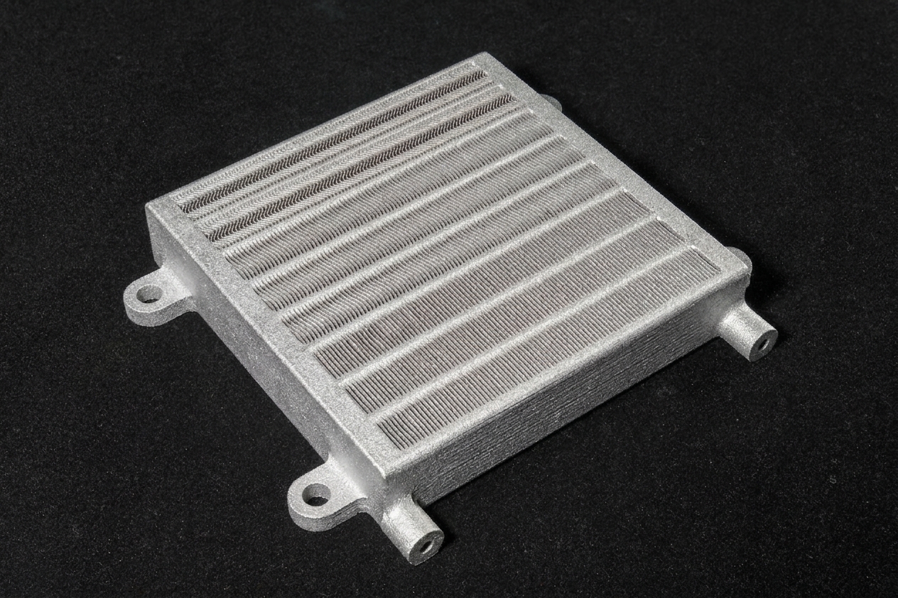
AlSi10Mg
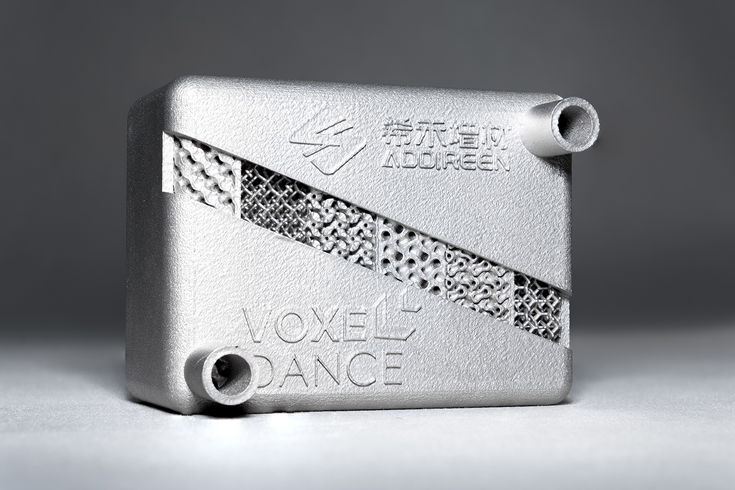
Lightweight aluminum alloy for EV heat exchangers, cooling channels, housings, and structural mobility components.
316L Stainless Steel
Custom stainless steel 316L 3D printing service for corrosion-resistant, complex and functional metal parts. Upload CAD for RFQ or request a design review for manifolds, brackets, tooling, medical, marine and industrial applications.
Designed for Pressure. Planned for Cleaning. Verified to Specification.
Qualification requirements are defined according to working pressure, fluid medium, temperature, cleanliness level, channel geometry and application risk.
Pressure Requirements
Working pressure, proof pressure, burst-pressure targets and holding time should be defined before manufacturing. Hydrostatic or pneumatic testing can be included according to the agreed specification.
Leak Testing
LPBF can reduce process plugs and assembly interfaces, but every pressure-bearing design still requires appropriate validation. Pressure-decay, fluid leak or other project-specific tests can be included.
Powder Removal
Powder escape paths and cleaning access are reviewed during DfAM. Internal channels can be cleaned through controlled air blasting, flushing, ultrasonic cleaning or other agreed processes.
Internal Inspection
Borescope inspection, CT scanning or sectioned-sample verification can be considered depending on channel diameter, geometry, component size and qualification requirements.
Particle Cleanliness
Where fluid cleanliness is critical, particle-count or gravimetric cleanliness testing can be arranged against customer-defined acceptance criteria.
Critical Interfaces
Ports, threads, sealing faces, mounting surfaces and other critical interfaces can be CNC-machined after printing to achieve the required dimensions and surface condition.
From CAD File to a Qualified Hydraulic Component
A structured engineering workflow helps identify manufacturing, cleaning and verification risks before production begins.
Submit Your Requirements
Upload a CAD file or 2D drawing and provide the working fluid, temperature, pressure, quantity and target delivery date.
Engineering and DfAM Review
We evaluate wall thickness, channel diameter, bend radius, unsupported geometry, powder escape paths, machining allowance and inspection accessibility.
Manufacturing and Test Proposal
You receive a proposal covering material, production approach, post-processing, critical machining, inspection scope and estimated lead time.
Printing and Post-Processing
The part is printed and completed through the agreed heat treatment, support removal, cleaning, CNC machining and surface-finishing processes.
Inspection and Testing
Dimensional inspection, internal-channel inspection, pressure testing, leak testing and cleanliness verification are performed according to the agreed scope.
Prototype Review and Repeat Production
Prototype results are reviewed before design iteration, repeat production or low-volume manufacturing begins.
Engineering Support Beyond Metal Printing
A functional hydraulic manifold requires more than a successful print. Design review, post-processing, cleaning, inspection and testing must be considered as one complete workflow.
Application-Oriented Engineering Review
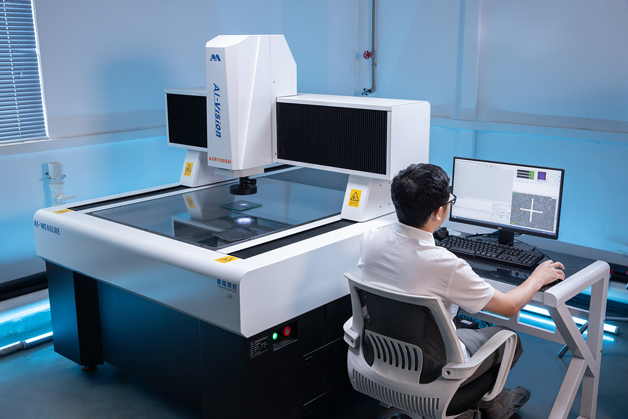
We begin with operating conditions and functional requirements—not only part geometry—to evaluate whether LPBF is appropriate for the project.
AlSi10Mg and 316L Capability
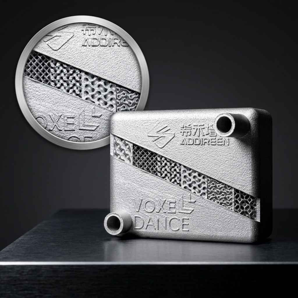
We support lightweight aluminum and corrosion-resistant stainless steel options for different hydraulic and fluid-control environments.
Printing and Post-Processing Coordination
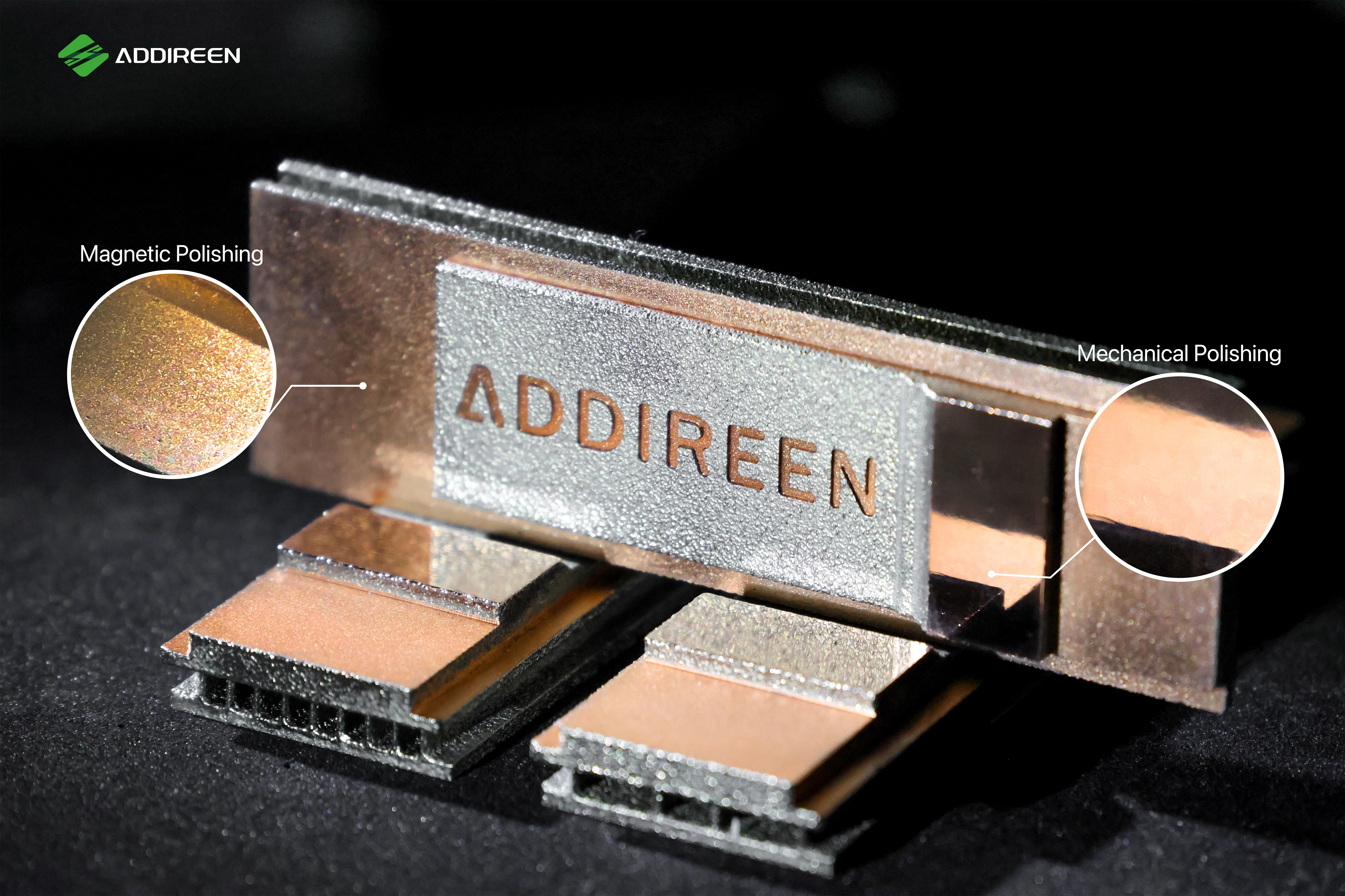
Printing, heat treatment, support removal, cleaning, CNC machining and inspection are planned around the final functional requirements.
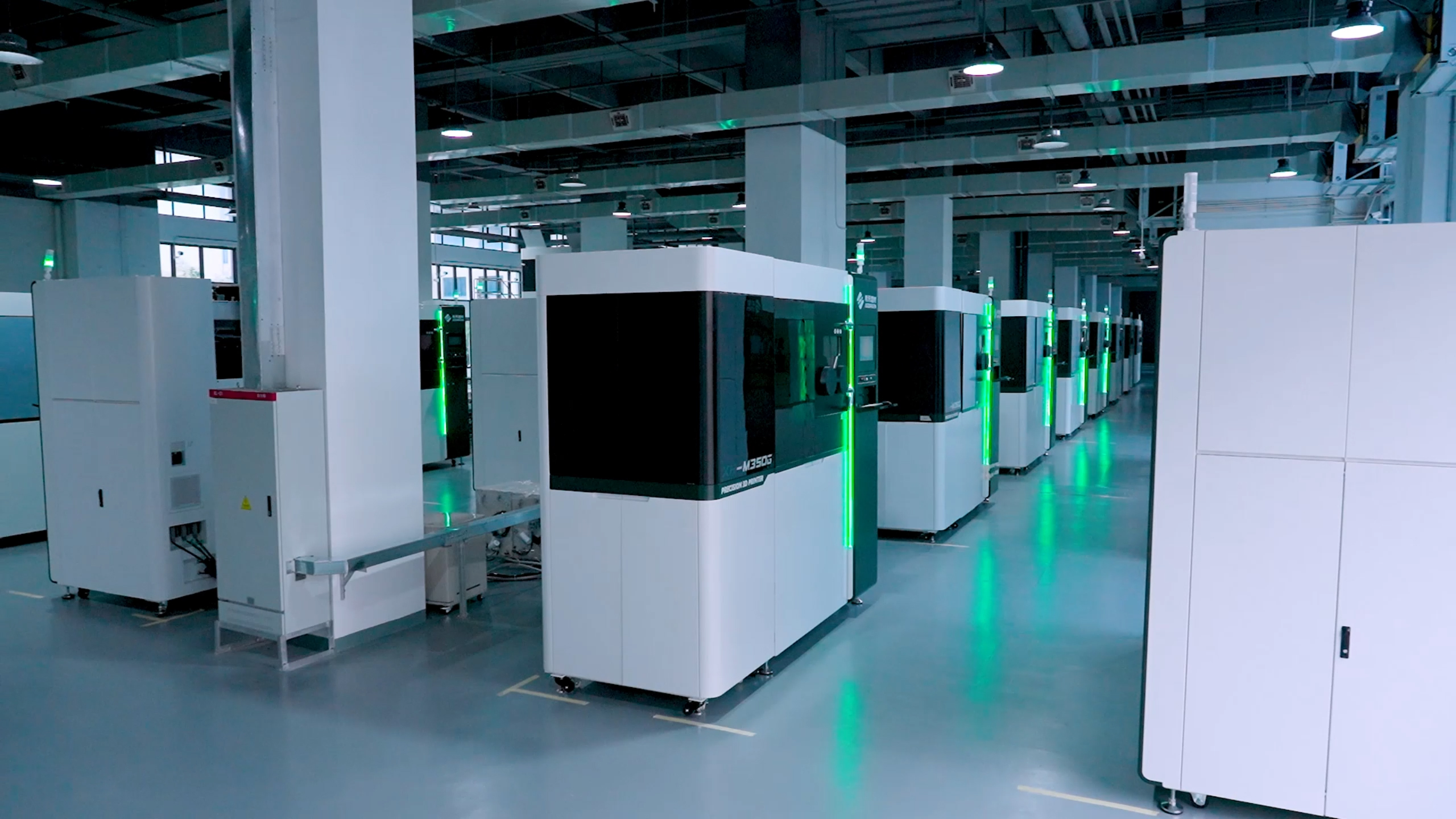
Prototype-to-Production Support
We support engineering prototypes, design iterations and repeat low-volume manufacturing after the process and acceptance criteria have been confirmed.
Frequently Asked Questions About 3D Printed Hydraulic Manifolds
Technical answers covering material selection, pressure validation, powder removal, machining and project quotation.
Start With a Hydraulic Manifold Feasibility Review
Upload a CAD file or 2D drawing and tell us your working pressure, fluid medium, temperature, quantity and target date. Our engineers will review material selection, printability, internal-channel accessibility, post-processing and verification requirements.