[Case Study] Designing 3D Printed Pure Copper Cooling Structures for Power Module Thermal Management
Designing 3D Printed Pure Copper Cooling Structures for Power Module Thermal Management
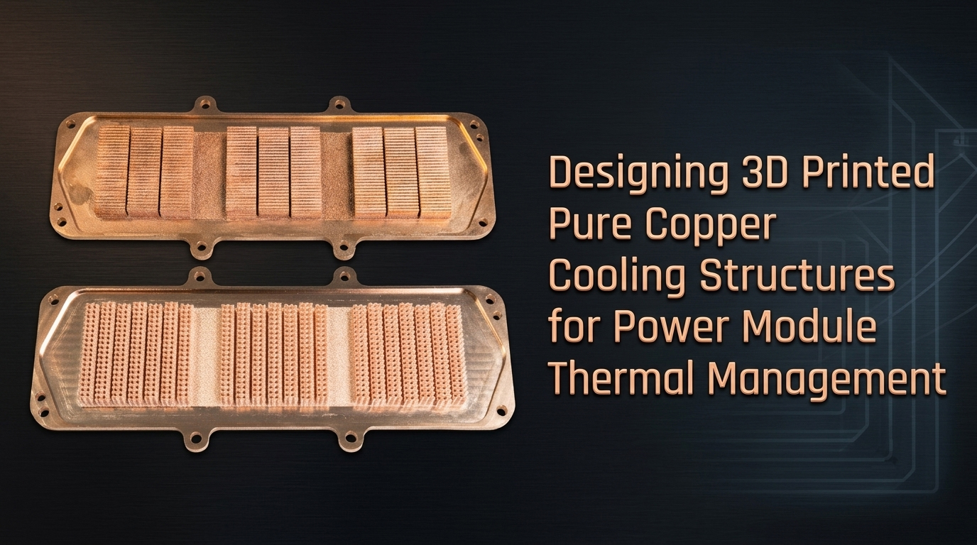
Power modules used in electric drive systems, power electronics, and high-current control units are pushing more heat into smaller packages. As power density increases, the cold plate is no longer just a support part. It becomes part of the thermal design.
This article is mainly about design: how green-laser pure copper 3D printing changes the way engineers can design liquid cold plates, heat exchanger , and internal cooling channels. The material and process matter, but the central question is what they allow the designer to do differently.
Milling, friction stir welding, stamping, brazing, and die casting can produce many reliable cold plates. They also tend to favor straight channels, parallel channels, or simple serpentine flow paths. These geometries are practical to manufacture, but they do not always match the heat flux distribution of a real power module.
Why conventional cold plates often constrain thermal design
Traditional cold plates are usually designed around what the process can make. This often works for standard heat loads, but it can become restrictive when the cooling structure must follow local hot spots or fit into a compact power module package.
- Tool size limits how fine pin fins or narrow features can be machined.
- Deep cavities and dense arrays increase the risk of tool interference or tool breakage.
- Die casting requires draft angles, limits geometric freedom, and depends on mold life and release feasibility.
- Brazed or welded assemblies introduce interfaces that must be managed for sealing, reliability, and inspection.
Pin-fin structures can increase heat transfer surface area and disturb laminar flow. The difficulty is not the thermal idea. The difficulty is making the feature size, spacing, density, and height that the simulation may suggest.
Why green laser matters for pure copper
Pure copper is attractive for thermal management because of its high thermal and electrical conductivity. It is also difficult to process with standard infrared laser systems because copper reflects much of the incident energy and conducts heat away quickly.
Green-laser powder bed fusion addresses part of this processing problem by improving laser energy absorption. A 532 nm green laser reaches about 40% absorptivity on copper, roughly 8 times higher than near-infrared laser absorption under comparable reference conditions.
That higher absorption does not remove the need for process control. Powder quality, scan strategy, layer thickness, thermal history, geometry, and post-processing still matter. It does, however, give the process a more stable starting point for producing dense copper parts with functional internal structures.
From process-first to performance-first design
With metal 3D printing, the design workflow can be reversed. Instead of starting with the limits of machining or tooling, engineers can start with the thermal target, use CFD to develop the flow path, and then manufacture the structure directly.
This does not mean every simulated geometry should be printed as-is. A good design still needs manufacturability review, including wall thickness, powder removal, support strategy, cleaning, pressure drop, sealing surfaces, and inspection access.
The useful change is that more of the design effort can be spent on thermal performance instead of fitting the design into a machining envelope.
Design options enabled by copper additive manufacturing
|
Design direction |
Feasibility with conventional processes |
What 3D printing enables |
|
Branching or dendritic channels |
Not practical for most conventional cold plate processes |
Multi-level branching with more flexible flow distribution |
|
Spiral or swirl flow channels |
Very difficult, especially with variable pitch |
Custom helix angles, variable pitch, and local flow control |
|
Pin-fin or lattice infill |
Often requires simplified features or secondary assembly |
Monolithic internal porous or lattice-like heat transfer structures |
|
Asymmetric inlet/outlet layout |
Constrained by planar flow paths and joining requirements |
Layout can be adapted to module packaging and hot spot locations |
|
Independently zoned flow circuits |
Difficult to seal and isolate in a compact part |
Multi-inlet and multi-outlet circuits can be integrated in one printed component |
Topology-optimized and conformal cooling channels
Power modules often have uneven heat flux distribution. The central area or specific chip positions may carry the highest thermal load. Instead of using the same channel everywhere, a topology-optimized design can direct coolant toward hot spots.
Conformal cooling keeps the channel path close to the heat source geometry. In a power module, this can mean maintaining a more consistent channel-to-die distance across multiple chip positions. The goal is not only to reduce peak temperature, but also to reduce temperature variation across the module.
Variable cross-section channels
Channel cross-section can be adjusted along the flow path. For example, a larger section near the inlet may help maintain flow rate where coolant is cooler, while a smaller section near the outlet can increase residence time and improve heat pickup. This type of design needs pressure-drop evaluation because the value comes from balancing temperature uniformity, heat transfer, and pumping power.
Monolithic multi-layer channel architecture
Additive manufacturing can place different flow functions in different vertical layers within one part. One example is a two-level cold plate: an upper layer for flow distribution and splitting, and a lower layer for localized high-intensity cooling close to the heat source.
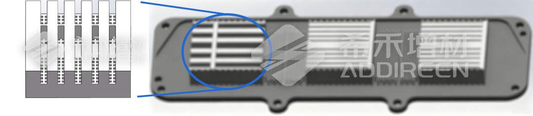
Fig. 1. Multi-layer flow channel concept from the source document. This image fits the section on vertical flow zoning.
TPMS structures
TPMS, or triply periodic minimal surface structures, provide continuous internal surfaces with high surface area and interconnected flow paths. In liquid cooling, TPMS structures can force coolant to change direction repeatedly, refresh near-wall fluid, and disturb the thermal boundary layer.
For heat transfer, the value is not only extra surface area. It is also the way the structure reshapes local flow behavior. That is why TPMS is often discussed for 3D printed heat exchangers and high-performance liquid cold plates.
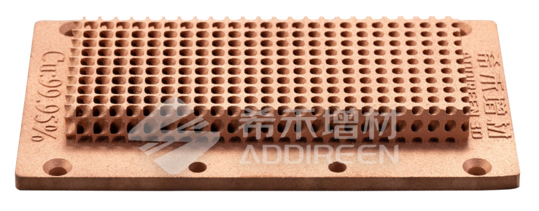
Fig. 2.TPMS structure
Reference performance data from optimized cold plate designs
Two example studies comparing optimized internal cold plate structures against a conventional baseline. Actual results depend on geometry, coolant condition, flow rate, heat source layout, material condition, and test method.
Staggered channel structures
Under an 8,000 W heat source, two optimized staggered-channel configurations were compared with a conventional structure.
|
Configuration |
Reported result |
Engineering interpretation |
|
Configuration A |
Peak temperature reduced by 9 deg C; flow resistance reduced by 20% |
Three-dimensional staggered channels increased heat transfer area while improving the flow path. |
|
Configuration B |
Peak temperature reduced by 11 deg C |
Stronger channel disturbance and secondary flow improved heat transfer coefficient, with a focus on thermal performance. |
The useful point is not that staggered channels are always better. The useful point is that additive manufacturing allows the engineer to tune the flow field in three dimensions. Depending on the system target, the design can be biased toward lower peak temperature, lower pressure drop, or a balance between the two.
Teardrop-profile heat transfer features
Under a 5,000 W heat source, two teardrop-based configurations were compared with a conventional structure.
|
Configuration |
Reported result |
Engineering interpretation |
|
Configuration A |
Peak temperature reduced by 10 deg C |
The teardrop profile guided smoother flow transition and allowed more heat transfer features at similar flow resistance. |
|
Configuration B |
Peak temperature reduced by 7 deg C; flow resistance reduced by 2 kPa |
Combining teardrop features with a staggered layout improved heat transfer while slightly reducing pressure drop. |
This is a good example of why shape matters in liquid cooling. A fin is not only added surface area. Its profile affects separation, mixing, local turbulence, and pressure loss.
What this means for power module cooling
For power module thermal management, the most useful benefit of pure copper additive manufacturing is not simply more complex geometry. Complexity only matters when it solves a measurable problem.
- Lower peak device temperature
- More uniform temperature across multiple chips
- Lower thermal resistance from chip to coolant
- Controlled pressure drop
- Reduced part count
- Shorter design iteration cycle
- Better use of limited packaging space
Pure copper 3D printing is useful when the cooling path needs to follow the heat source more closely than conventional manufacturing allows. It can also be useful when internal features, such as TPMS structures, microchannels, staggered channels, or multi-layer flow circuits, need to be built as one integrated component.
For some projects, aluminum or CuCrZr may be a better choice depending on strength, weight, cost, heat treatment, or operating temperature. Material selection should be tied to the thermal load, mechanical load, environment, and post-processing requirements.
Design information needed before quoting a copper cooling part
Before quoting a 3D printed pure copper liquid cold plate or heat exchanger, it helps to prepare the following information:
- STEP or STP file
- 2D drawing if tolerances or sealing surfaces are important
- Heat source power and heat flux distribution
- Coolant type, inlet temperature, flow rate, and pressure limit
- Target temperature or thermal resistance
- Quantity and lead time requirement
- Post-processing needs, such as CNC machining, polishing, cleaning, or leak testing
- Inspection requirements
- Any restrictions on size, weight, mounting, or packaging
Early review is important because internal channel design affects not only thermal performance but also powder removal, cleaning, sealing, and inspection.
Conclusion
Green-laser pure copper 3D printing gives thermal engineers more freedom to design around the heat source instead of around a machining process. For power modules, this can make it possible to build cold plates with staggered channels, teardrop heat transfer features, multi-layer flow paths, TPMS structures, and conformal cooling paths.
The performance data in the source examples shows why this matters. In design-specific comparisons, optimized copper cold plate structures reduced peak temperature by 7 to 11 deg C, with one case also reducing flow resistance by 20% and another reducing pressure drop by 2 kPa.
Those numbers should not be treated as automatic outcomes. They show the direction of value: when material, geometry, and flow design are developed together, metal 3D printing can turn thermal simulation into manufacturable copper cooling hardware.
If you are evaluating pure copper 3D printing for a cooling component, the next step is usually not a quote alone.
- Review the thermal management white paper for more data, design considerations, and application examples for 3D printed cooling components.Please visit
https://www.addireennow.com/en/green-laser-copper-thermal-management/ad64d
- See how Addireen applies metal 3D printing to liquid cold plates, heat exchangers, heat sinks, and high-conductivity thermal modules.Please visit
https://www.addireennow.com/en/industries/advanced-thermal-management/c44da
- Submit your cooling component design for manufacturability review, material feasibility, post-processing planning, and quotation. Please visit
https://www.addireennow.com/en/quote