R&D Deep Dive: Thermal Performance and Build Specs of 3D-Printed Copper and Aluminum Heat Exchangers
3D Printed Liquid Cold Plates: Flow Channel Redesign and Manufacturing Parameters
In thermal management research, liquid cooling designs frequently encounter non-standard dimensions and strict spatial constraints. Conventional machining and brazing methods hit a bottleneck when attempting to balance high thermal conductivity with a compact footprint.
We recently analyzed a metal 3D-printed liquid cold plate sample. Moving beyond the conceptual phase of metal additive manufacturing, we evaluated this component's baseline performance for thermal research, focusing strictly on its fluid logic, structural geometry, and actual manufacturing data.
From Multi-Part Assembly to Single-Piece Construction
Conventional liquid cold plates are brazed or welded assemblies consisting of fins, baffles, side panels, fittings, and seals. These multiple seams increase the risk of leaks under sustained high-pressure flow. Furthermore, thermal contact resistance at these joined interfaces is unavoidable, regardless of the welding process.
This 3D-printed cold plate is manufactured as a single part, eliminating all assembly and welding steps. This mitigates the risk of seam leaks and physically removes interfacial thermal resistance, allowing heat to conduct directly through a continuous metal lattice.
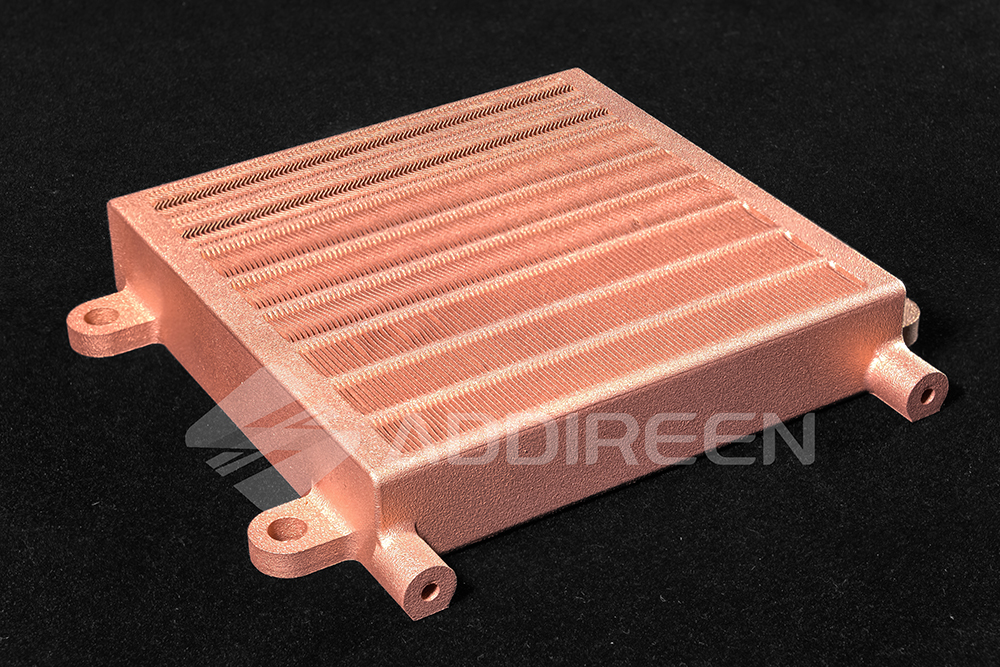
Figure 1. Addireen 3D-Printed Pure Copper Liquid Cold Plates.
Flow Resistance Control and Corrugated Fin Design
The core heat transfer zone utilizes densely packed, thin corrugated fins. This geometry increases the surface area within a confined volume. As fluid passes over these undulations, it generates localized turbulence, disrupting the thermal boundary layers that typically form in straight channels.
Because high-density fins inherently increase flow resistance, the internal layout incorporates multiple parallel flow channels. This configuration maintains the overall system pressure drop within a workable range, allowing standard-capacity water pumps to drive the fluid circulation.
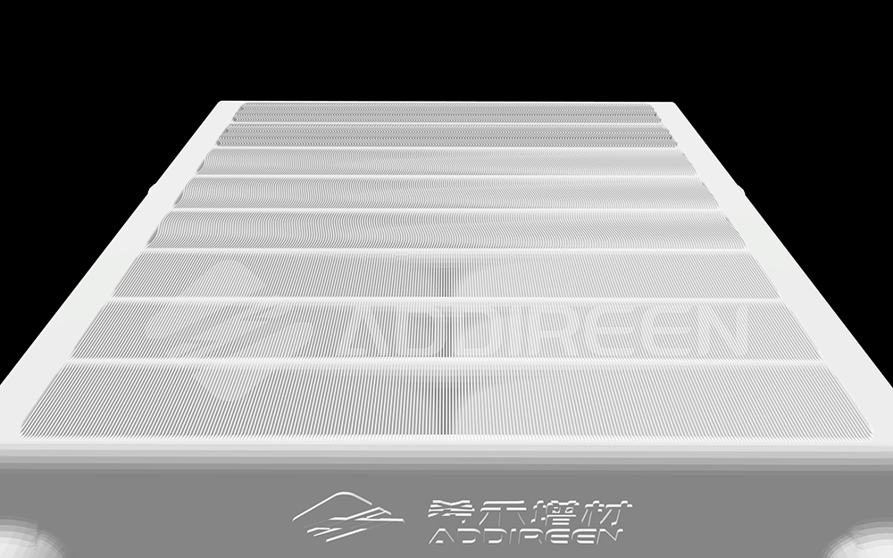
Figure 2. Internal parallel flow channels and densely packed corrugated fin geometry.
Additive Process and Powder Removal Considerations
The design of testing components must align with both thermodynamics and Design for Additive Manufacturing (DfAM) principles.
- Self-Supporting Structures: The channel tops utilize a self-forming roof design, with walls oriented perpendicular to the build plate. This yields high internal surface quality and requires zero internal solid supports, resolving the issue of removing support material from blind holes.
- Direct-Connect Geometry: Fins and channel walls are integrally printed. This provides the structural stiffness required to withstand fluid pressure while facilitating direct heat transfer.
- Powder Clearing Channels: To address the powder removal challenges inherent in powder bed fusion, channel spacing is strictly set at 1.5 mm. Paired with a parallel, straight-through layout, this ensures unfused powder is thoroughly evacuated, preventing loose particles from detaching and clogging the system during liquid operation.
Manufacturing Limits and Measured Parameters (Pure Copper vs. Aluminum Alloy)
Unrestricted by tool clearance or stamping deformation, monolithic metal 3D printing enables thinner wall structures. To accommodate specific thermal loads and project budgets, both pure copper and aluminum alloy variants are available. The measured production data is as follows:
- Pure Copper Variant (Processed via Green Laser 3D Printing): The core heat transfer zone achieves a minimum wall thickness of 0.1 mm. Measured thermal conductivity is stable at 400 W/(m·K), with electrical conductivity reaching 100% IACS. This targets high heat flux environments or compound testing conditions requiring high current conduction and high-frequency signal transmission.
- Aluminum Alloy Variant: Minimum wall thickness is maintained at 0.3 mm, with an internal surface roughness (Ra) of 8 μm and a relative density of 99.9%. Following a 300 °C/2 h annealing process, thermal conductivity reaches 185 W/(m·K). This variant prioritizes weight reduction and cost-efficiency.
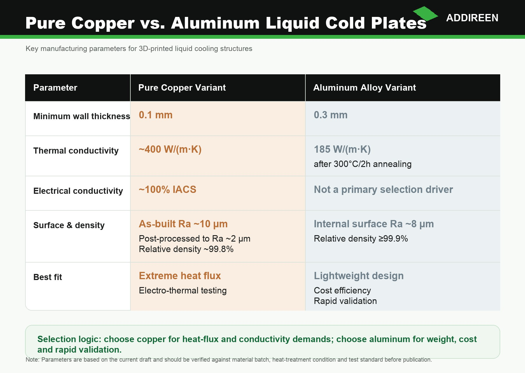
Figure 3. Pure copper prioritizes high thermal and electrical conductivity for high-heat-flux or electro-thermal testing conditions, while aluminum alloy provides a balanced option for lightweight and cost-sensitive thermal designs.
Hardware Support for Thermal Management Research
Thermal management experiments frequently require iterative adjustments to external physical interfaces and internal topological channels. Tooling-free manufacturing enables the direct physical realization of components from CAD models, fulfilling the requirement for rapid prototyping. This provides practical hardware support for fundamental thermal research and fluid dynamics verification.
- For a detailed evaluation of material properties and process standards relevant to your project, please refer to our Material Specifications.
- To explore further applications, review our Advanced Thermal Management Solutions.
We provide an end-to-end manufacturing workflow, encompassing early-stage channel printability assessment, thermal structure design, customized powder removal strategies, and final post-processing services, including CNC precision machining and inspection. If your R&D team is developing lightweight thermal management systems, contact us for a technical review to receive a tailored process and material evaluation.
Metal 3D Printing Service Platform: https://www.addireennow.com

Figure 4 End-to-End Additive Manufacturing Workflow: From CAD review, manufacturability assessment, and DfAM optimization, to precision printing, post-processing, and final inspection.